Autocad 2019 2d Drawing Elevations Aroung a Plan
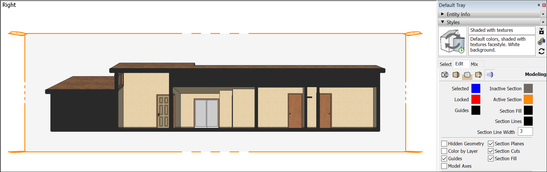
In SketchUp, section planes cut a model along a plane so that you can peer inside the model - without moving or hiding any geometry. In a 3D model, an active section plane hides everything on one side of the plane, as shown in the following figure.
You can use section planes for all types of applications:
- Cut a building horizontally to see the floor plan. In architectural drawing, this two-dimensional top-down cut is called a planimetric view.
- Cut a building vertically to see inside the rooms of several floors at once. This type of cut is called a sectional view (not to be confused with SketchUp's section planes).
Tip: To create a planimetric view like an architect, place the section plane 48 inches above the floor's surface. This placement usually enables you to see windows and doors in the slice without cutting through countertops or furniture. To create a sectional view, don't cut through columns, because they'll look like walls instead of objects that people can walk around; do cut through stairs or elevators, because this shows how people move through the building.
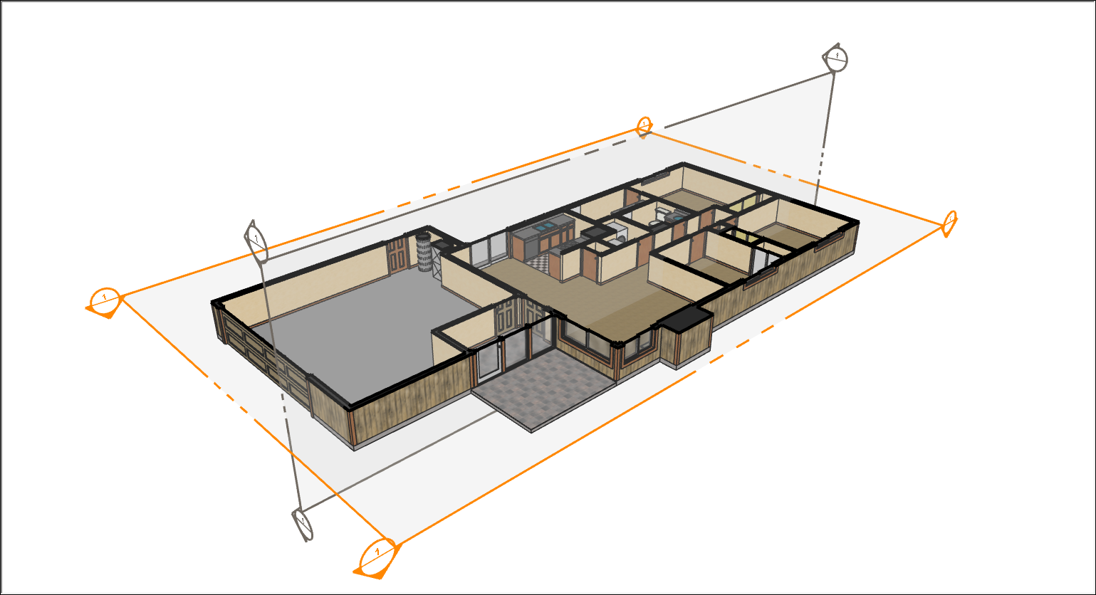
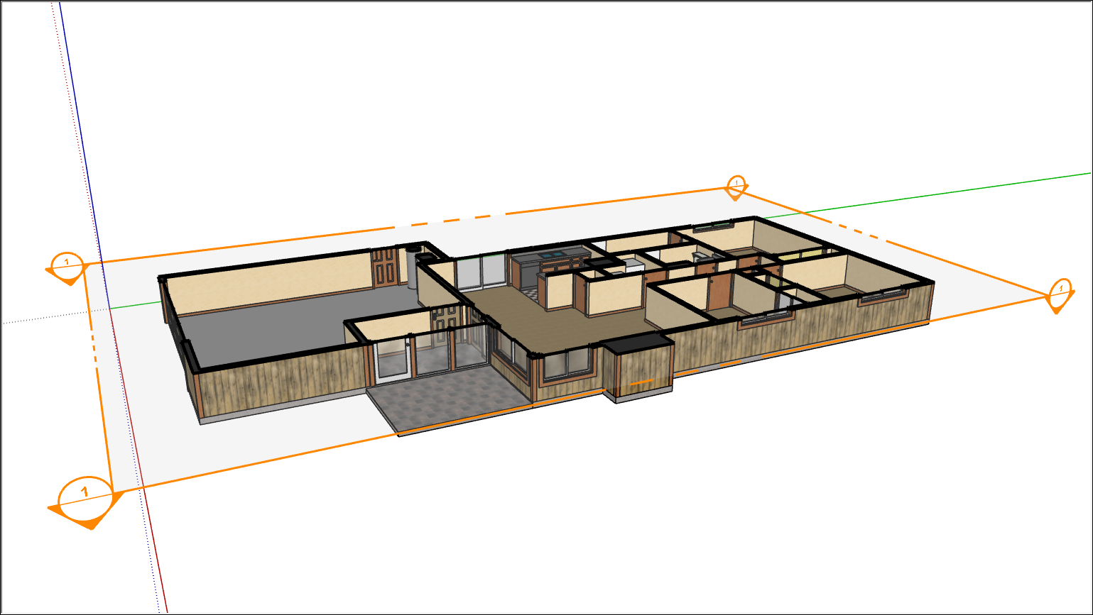
In SketchUp, you can insert multiple section planes, but only one section plane can be the active cut in each context. You create more than one context in a model by creating groups or components, each of which has a separate context. For example, the following model is a component and has two section planes; the section plane that shows the plan is active.
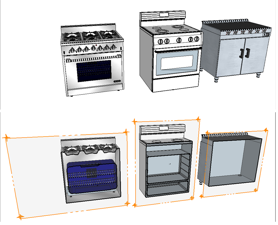
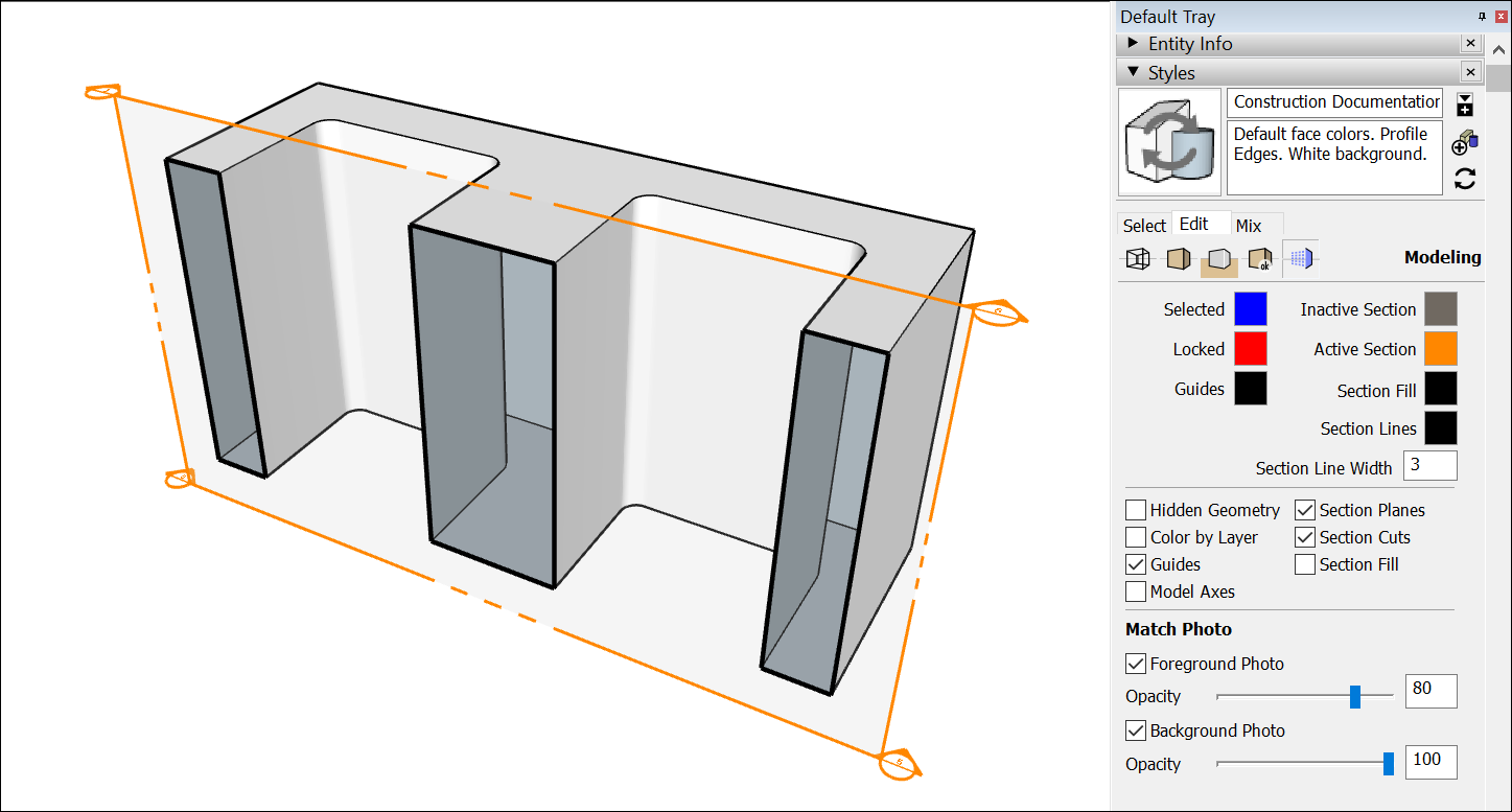
Another example is this model that contains several ovens. Each oven is a separate group, as shown in the following figure. You can display an active section plane in each group to see that none of the ovens contains a warm apple pie or chocolate chip cookies. (Darn it!) See Grouping Geometry and Creating a Basic Component for details about creating groups or components and how to open or close a group or component context.
Tip: Want to show off multiple interior views of a model? SketchUp enables you to show section cuts in scene animations. To animate scenes that show different section cuts, you need to save the section settings in a style and then save each view in a scene. Animating Scenes explains how to create animations of your model.
The following video introduces you to section planes and gives you a sneak peek at section plane animation. In the upcoming sections, you find detailed steps that walk you through the many things section planes can do.
Table of Contents
- Adding a section plane
- Filling voids in section cuts
- Creating new geometry from a section plane
- Showing or hiding section planes, cuts, and fills
- Exporting section cut effects
Adding a section plane
Inserting a section plane is easy as pie. Make sure nothing in your model is selected, and open the group or component context where you want to add the section plane. Also, if you want to place the section plane at a specific height, such as 48 inches above the floor surface, use the Tape Measure tool to set a guide line that will help you place the section plane precisely where you want it.
When you're ready to add a section plane, follow these steps:
- Select the Section Plane tool (
 ) or select Tools > Section Plane. Microsoft Windows users find the Section Plane tool on the Sections toolbar. On both Microsoft Windows and Mac OS X, the Section Plane tool is on the Large Tool Set palette.
 - With the section plane cursor, shown in the following figure, click a face to place your section plane.
Tip: If you have trouble keeping the section plane in your desired orientation, hover over a face that matches the orientation you want and hold down the Shift key to lock the section plane cursor's direction. You can also tap the arrow keys to orient the normal of the section plane to the default axes directions: Up for Blue axes, Right for Red axes, Left for Green Axes, and Down for parallel to face.
- Adjust the placement with the Move tool or the Rotate tool.
- Reverse the cutting direction by context-clicking the section plane and selecting Reverse from the menu that appears. For example, if you make a vertical cut, you can reverse the cut to display the inside of the other half of your building.
- Align SketchUp's camera with the section plane by context-clicking the section plane and selecting Align View. In the preceding figure, aligning the view to your section plane takes you to a top view of the model.
- Select which section plane is the active cut, if you have more than one, by context-clicking the section plane you want to make active and selecting Active Cut from the menu. Or, double-click the section plane you'd like to activate or deactivate.
- Control section plane visibility. See details about hiding or showing section planes later in this article.
Tip: Want a quick way to manage your section planes? Each section plane appears in the Outliner panel with the name you entered when you created the section plane. You can edit the section plane's name and symbol in the Outliner or the Entity Info panel.
In the Outliner, you can also context-click a section plane and use the menu that appears to hide, activate, reverse, and take other actions to manage that section plane. Double-clicking the name in the Outliner activates or deactivates the section plane.
Note: When you use the Align View command in Parallel Projection perspective, you can quickly generate sectional elevation or one-point perspective views of your model.
Filling voids in section cuts
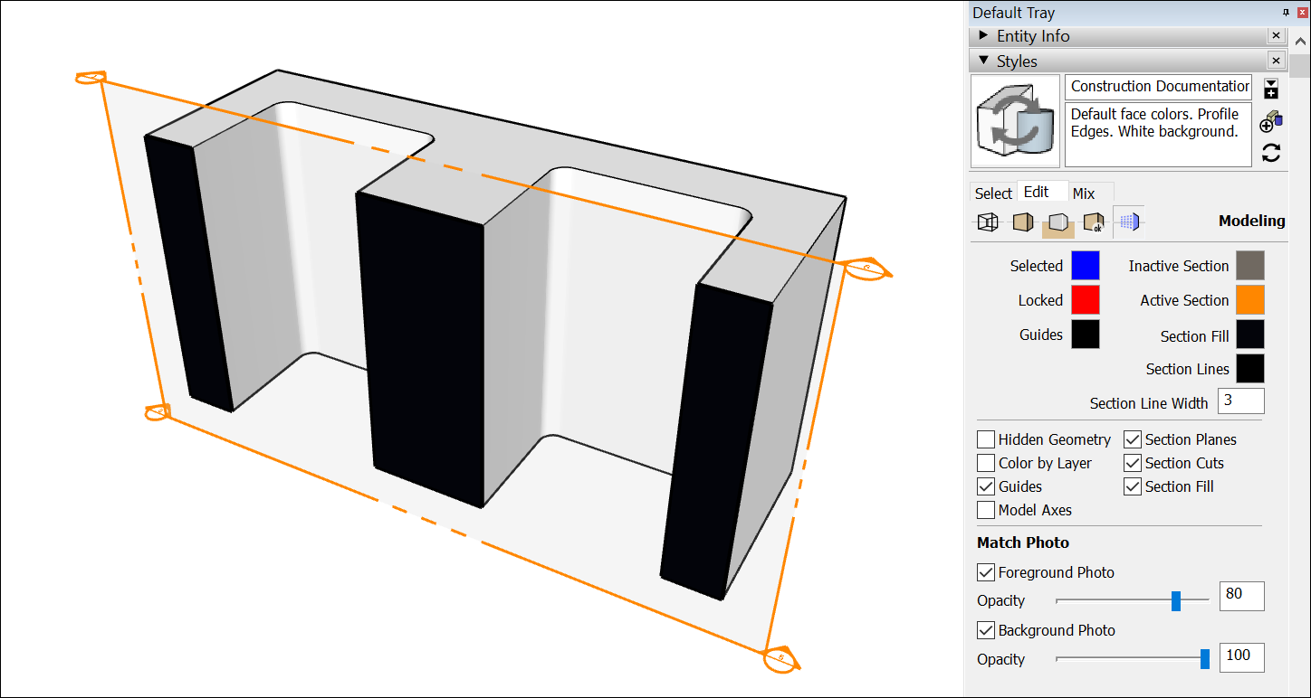
When you slice a solid with a section plane, you may not want to see voids where solid material should be. For example, say a section plane is showing a sliced concrete block. Depending on your section fill settings, the model might show empty space where the concrete block would be filled.
To fill closed loops in the slice, you can simply select the Section Fill check box in the Styles panel. For example, the following figure shows how the concrete block changes when the Section Fill check box is selected. Alternately, you can toggle section fill visibility with the View > Section Fill command or the Display Section Fill button ( ) on the toolbar. (Remember that whether you use the Styles panel, View menu, or toolbar buttons, you modify the style and need to save the style if you don't want to lose the visibility settings you've applied.)
To control the Section Fill settings in the Styles panel, follow these steps:
- Open the Styles panel.
- Click the Edit tab.
- On the Edit tab, click the Modeling Settings icon (
 ).
). - To fill areas that are closed loops, select the Section Fill check box. Remember that, to create a filled section cut, the geometry in the section slice must form a closed loop within its group or component hierarchy. You can see that hierarchy in the Outliner.
- (Optional) To adjust the color, click the Section Fill color swatch and use the color picker to choose your desired color.
Tip: Need some help troubleshooting a fill? Context-click the section plane and choose Troubleshoot Section Fill. You then see red circles around the vertices that border the opening in the loop.
See Customizing Modeling Settings to Complement a Style for more details about your Modeling Settings options.
Creating new geometry from a section plane
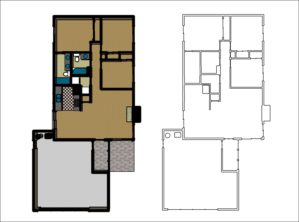
Where a section plane intersects with a model, SketchUp enables you to create geometry, which is automatically organized into a group. You can then move that group to a new location in your model, so you have a copy to work with, as shown in the following figure. Or explode the group so you can use the geometry to divide your model.
To create geometry in this way, context-click a section plane and select Create Group from Slice from the menu that appears.
Tip: If you have trouble seeing or selecting the group, select the group in the Outliner.
When a section plane cuts your model, the cut isn't permanent, and you can control the visibility of the plane and the cut independently of each other. Hiding the section plane makes the transparent plane with its color handles disappear. Hiding the section cut makes your model look whole again.
Here's how to control the visibility of your section planes and cuts:
Tip: Microsoft Windows users can find all the section tools on the Section toolbar. Mac OS X users can add section tools to the main toolbar. See Customizing Your Workspace for details.
Exporting section cut effects
No matter what version of SketchUp you have (Make or Pro), you can export an image of your model displaying section cut effects. You can use these images in portfolios, presentations, websites, or basically anywhere you might want to show off an image of your work. Just make sure your model shows the section cut as you want it to appear in your image. See Using SketchUp Data with Other Modeling Programs or Tools for details about exporting a model as an image or other file type.
PROWith SketchUp Pro, you can also export a section slice, which is a 2D vector image of geometry along a section plane. Here are a just a few ways you might use a section slice:
- Create scaled drawings in a CAD program. If you created a 3D model with precise measurements and angles, the section slice feature enables you to scale the slice. (Technically, you can scale imprecise models, too; the scale just doesn't mean anything.)
- Edit the slice as a vector image. Because the 2D slice is exported as a vector graphic, you may be able to open the exported file in programs like Adobe Illustrator.
Tip: When the scale of your 2D slice is important, pay close attention to your view in SketchUp. If your view is set to Perspective, you can't export to scale. If you're viewing your model in Parallel Projection view, only faces whose normals are perpendicular to the view angle are measurable. Viewing a Model explains what the different views show and how to change your view.
PRO To export a section slice from SketchUp Pro, follow these steps:
- If your section plane is within a group or component context, double-click the group or component to open its context.
- Select the section plane with the section cut that you want to export.
- Select File > Export > Section Slice. The Export 2D Section Slice dialog box appears, as shown in the following figure.
- Choose where you want to save the file. By default, the file is saved in your Documents folder.
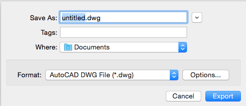
- Type a name for the exported file in the File Name box (Microsoft Windows) or Save As box (macOS).
- Select what type of file you want to export from the Save As Type box (Microsoft Windows) or Format box (macOS). The default option is
.dwgor you can select.dxf. Both of these are AutoCAD file types. - (Optional) Click the Options button to open a dialog box where you can select your options. The following list outlines what your options mean. After you're done selecting options, click OK to return to the Export 2D Section Slice dialog box.
- Click the Export button. Your file is saved in the location you selected in Step 4.

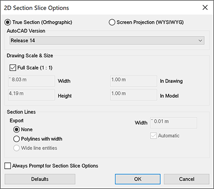
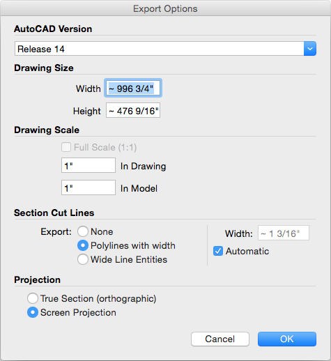
When you export a 2D slice, you can choose from the following options:
- True Section (Orthographic) exports the section slice as a true orthographic drawing. This is useful for creating templates for CAD drawings or any other time you want to generate accurate, measurable slices.
- Screen Projection projects the section cut as you see it on your SketchUp screen, including any perspective distortion. This is most useful for diagrams that you don't need to measure.
- AutoCAD Version enables you to select the version of AutoCAD you plan to use from the drop-down list.
- Drawing Scale and Size options enable you to configure the scale of the exported section slice. If Full Scale is selected, SketchUp exports the file at a 1:1 scale. The In Drawing and In Model options enable you to specify a drawing scale, where In Drawing is the measurement of the exported geometry and In Model is the object's actual measurement. For example, for a scale of 1:4, enter 1" in the In Drawing box and 4" in the In Model box.
- Section Lines options enable you to choose how the section cut lines in your exported slice appear. None exports the lines at normal width. Polylines with Width turns the lines into polylines. Wide Line Entities (only available when exporting
.dwgfiles to AutoCAD 2000 or later) makes the lines in the exported file wider than normal. If you want to set the line width automatically, leave the Automatic checkbox selected. Or clear Automatic and enter a value in the Width box to set an exact line width.
On Microsoft Windows, you also see Section Line options for separating profile edges on a layer and always being prompted for section slice options.
- The Separate on a Layer option creates a single additional layer for profile edges. This layer is useful if you would like to plot profile lines using a different pen weight or quickly change the line width of all profile lines in a separate CAD or illustration program.
Tip: The Separate on a Layer option is different from layer assignments in SketchUp. SketchUp Layer assignments do not translate directly when exporting 2D hidden line vectors.
- Select the Always Prompt for Section Slice Options checkbox, and SketchUp displays the 2D Section Slice Options dialog box every time you export a section slice. When this checkbox is cleared, by default, SketchUp uses whatever options were selected last time.
villarrealpards1950.blogspot.com
Source: https://help.sketchup.com/en/sketchup/slicing-model-peer-inside
0 Response to "Autocad 2019 2d Drawing Elevations Aroung a Plan"
Post a Comment